Building instructions
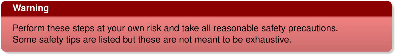
1. Custom parts: camera and mirror holders
Required tools and parts:
-
3D printer (e.g. Ultimaker 2)
-
3D printing material (e.g. Velleman PLA3B1)
-
file, scalpel or other small knife
-
camera holder STL file: cam_holder.stl
-
mirror holder STL file: mirror_holder.stl
Use the software for your 3D printer (e.g., Cura for Ultimaker) to convert the STL files to a format your printer understands. After printing clean up parts with file or scapel; try to fit camera into holder (fit should be tight); and file side clips until camera fits in holder.
Depending on the printer it might be useful to modify the designs such that minimal filing/cutting is required after printing. A folder with source files (in OpenSCAD format) is available in the mousecam repository in the same subdirectory as the STL file folder.
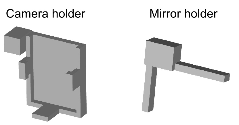
Note: A newer version of the Adafruit 1937 module is available which is a big thicker (about 3.1 mm). The below figure shows top and bottom views of the old an new camera modules. It seems that the main change is that some components were moved to the bottom of the module (see new module, bottom view). Updated STL files (with suffix “_new_module.stl”) can be found in the stl folder.
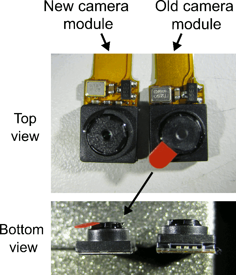
2. Removal of the infrared filter
The camera module has an IR filter which needs to be removed when using IR light illumination. The filter is attached to the back of the lens. The lens can be removed by carefully turning it counter-clockwise with small pliers or big forcepts. Removing the lens will expose the camera sensor (see below picture, left). If possible avoid getting any dirst, dust etc on the camera sensor.
The IR filter is a thin round piece of glass (see below picture, middle) and can be removed by levering it off using a sharp knife (e.g., a scalpel blade) as indicated by the red arrow. It is possible to get it off in one single piece but if you break it don’t worry – just remove everything (e.g., using some air duster) and make sure the lens is clean (below picture, right).
3. Assembling of the camera system
Note: construction of the camera system requires some off-the-shelf parts. We provide example parts (supplier/item) as used in the above paper but other parts might work as well.
Required parts and tools:
-
Camera and mirror holders (see custom parts above)
-
21 G steel cannula (e.g., Coopers Needle Works). We successfully used thin-walled steel cannulas but other cannulas (e.g., a 21 G syringe needle after cutting the tip) will also work.
-
Infrared (IR) mirror (e.g., Qioptiq Calflex-X)
-
Small IR LED (e.g., Vishay VSMB2943GX01)
-
Small resistor, 150–200 (e.g., Farnell Multicomp, package 3216)
-
2 x 30–36 AWG wire (e.g., Alpha Wire 2936); length $\approx$ 5 cm
-
Miniature connectors for connecting the camera system to the implant/skull (e.g., Omnetics A79007-001/A79010-001 or 8-pin Mill-Max connectors)
-
optional: 2 x female gold pin (e.g., RS Components 481-500)
-
Dremel (e.g. Proxxon D-54518) with cutting disc (e.g. wheel no. 409) and 0.8 mm drill bit (DU68.10)
-
glass cutter; most glass cutters should work. We successfully used this one.
-
2 combination pliers; if available 1 self-locking hemostat pliers
-
A length measuring device (e.g., ruler or caliper)
-
A thin and straight solid object, e.g., a metal ruler, for guiding glass cutter
Steps:
-
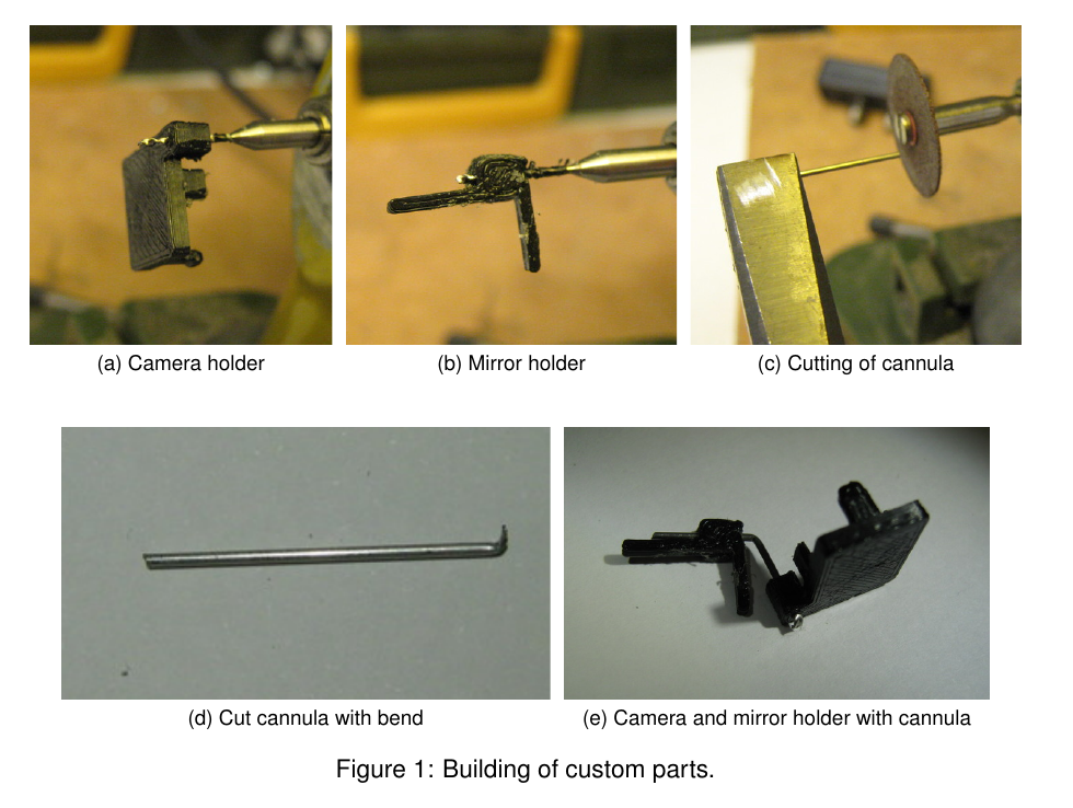
Drill hole in the camera holder with Dremel and 0.8 mm drill bit (Figure 1a). Use hemostat or other pliers (not shown in photo) to hold the camera holder while drilling.
-
Drill hole in the mirror holder (holding it with pliers) using Dremel and 0.8 mm drill bit (Figure 1b).
-
Cut cannula (21 G) to approx. 2 cm with cutting disc on Dremel (Figure 1c). Use safety glasses and hold both ends with pliers. Bend with second pliers at one of the ends to give sharp bent tip (Figure 1d). The bent tip will be fixed with a drop of epoxy to the back of the camera holder later on to prevent the mirror holder from rotating around the axis of the cannula.
-
Push cannula from the back of the camera holder through the hole until the back of the camera holder hits the bent tip of the cannula.
-
Bend cannula in the middle (approx. 1 cm) by about approx. 60° using pliers. See Figure 1e) for a camera holder with mirror holder and bent cannula.
-
To cut the infrared (IR) mirror (e.g. Qioptiq Calflex-X 25 x 25 mm), first mark desired size (e.g., 7 x 7 mm for a relatively large field-of-view including eye and whiskers) with a removable marker. Score with glass cutter (along a thin solid object, e.g., a metal ruler) along one side of mirror. Break off scored line by holding both sides with pliers and carefully moving one pair up or down (wearing safety glasses). The mirror packing paper, a lens cleaning tissue, or some thin rubber sheet can be used to protect the mirror. Note: breaking glass is tricky and may occasionally result in a jagged edge; repeat until edge is satisfactory. Glue sharp side against mirror holder and cover outside with super glue or epoxy if necessary. It is also possible to use a file to get rid of sharp edges.
-
Glue cut mirror tile to 3D printed mirror holder. A very thin layer of super glue (e.g., Loctite Power Flex Gel) is sufficient to permanently fix the mirror to the mirror holder.
-
Put a very thin layer of super glue onto the cannula and gently push the cannula into the hole in the mirror holder. This will secure the mirror, but will still allow for positioning the mirror later on during calibration (see Calibration).
-
Attach LED with a tiny drop of super glue to the bottom of the camera holder.
-
Solder a current-limiting resistor to the anode (+) of the LED (unless it is simpler to solder the LED closer to the power source). The value of the resistor depends on the LED and the power source (there are plenty of on-line tools, e.g., this one, to calculate the resistor value). Secure LED and resistor using a thin layer of (transparent) epoxy.
-
Solder two thin wires (30–36 AWG) to the cathode (-) of the LED and the resistor. The length of the wire depends on the distance between the camera holder and the LED power source. For the Intan headstage used in the paper about 5 cm wires were long enough. Moreover, in order to quickly connect/disconnect the wires to/from the power source during experiments it might be useful to use miniature gold pins and sockets. Cut away the solder pots, solder the wires to the pin sockets and secure the wires with a tiny drop of epoxy. Finally, solder the corresponding pins to the power source (e.g., the solder holes of the Intan headstage).
-
Fix connector (e.g., Omnetics A79007-001 after cutting away solder tails) using super glue to the back of the camera holder. See Figure S1 in the paper for an example of a fully assembled camera system with connector.